
Configuration
Information to Configure and setup The Gabster TD1
and DC Offset can be found Below and also in the Videos on the right side here.
Please make sure you read the Important info on the Manual page
Please also View the Video about the Steps for powering the dac.
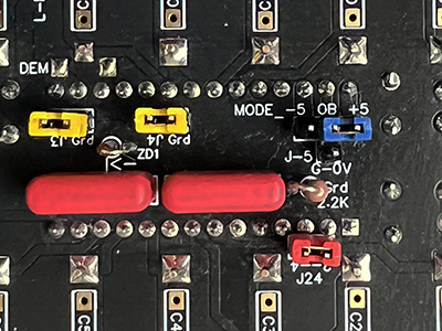
Running the Gabster TD1 in Regular mode and without a DEM capacitor
This mode uses the I2s signal as a DEM
For this mode you do not need to install a DEM Capacitor if one is present desolder and remove it.
NO I2s to PCM converter is needed or used.
J3 & J4 are ON J24 is ON Mode OB +5v On
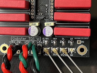
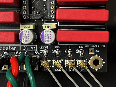
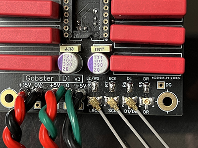
Connect 3 Ufl cables from (TD1) SCK LRCX D1/DL to (FifoPi) SCK LR SD/D1
DR on TD1 is not used in this case
Running the Gabster TD1 in Sim Mode (Gabster Recomended)
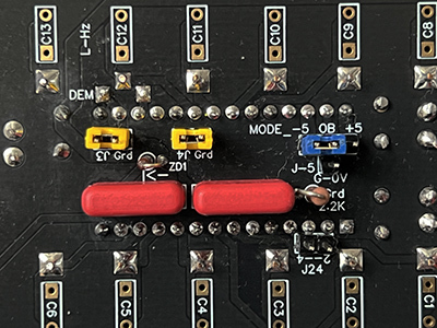
This mode uses a I2s to PCM converter board and the I2s signal as a DEM
For this mode you do not need to install a DEM Capacitor if one is present desolder it
A I2s to PCM converter is needed and the Jumper on it should be set to JOB.
J3 & J4 are ON J24 is OFF Mode OB -5v On
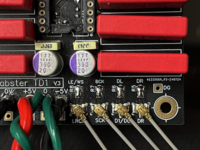
Connect 4 Ufl cables from (TD1) SCK LRCX D1/DL Dr to (PCM Conv) SCK LR DL DR
Folow the (I2S to PCM Converter) Manual for connection to the FifoPi
Running the Gabster TD1 in Differential (Balanced) Mode
This mode uses 2 Gabster TD1 Boards
This mode uses a I2s to PCM converter board and the I2s signal as a DEM
For this mode you do not need to install a DEM Capacitor if one is present desolder it A I2s to PCM converter is needed and the Jumper on it should be set to JOB.
J3 & J4 are ON J24 is OFF Mode OB -5v On
Install XLR Connectors to both Gabster TD1 Boards
All UFL cables must be the same legth
Both TDA1541A chips should be as similar as possible and in exact phase
Gabster TD1 Left Chanel Board
Connect 4 Ufl cables from (TD1) SCK LRCX D1/DL Dr to (PCM Conv) SCK LR DL DLn
Gabster TD1 Right Chanel Board
Connect 4 Ufl cables from (TD1) SCK LRCX D1/DL Dr to (PCM Conv) SCK LR DR DRn
Please note there are 2 additional SCK and LRCK terminals on the bottom side of the I2s to PCM converter by Ian
Folow the (I2S to PCM Converter) Manual for connection to the FifoPi

Running the Gabster TD1 in Regular mode and with a DEM capacitor
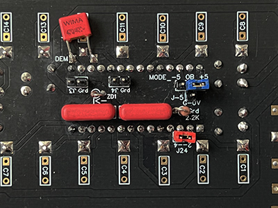
This mode was used often in most Vintage CD Players It uses a DEM Capacitor around 470pf. You need to solder one on the bottom Dem Pads See photo on the right
NO I2s to PCM converter is needed or used.
J3 & J4 are OFF J24 is ON Mode OB +5v On
Connect 3 Ufl cables from (TD1) SCK LRCX D1/DL to (FifoPi) SCK LR SD/D1
DR on TD1 is not used in this case
Replacing the RCA Connectors and XLR
The TD1 was designed to not use any Wires in the audio path (the best wire is no wire) It uses direct soldered RCA Gold Plated Brass connectors to the board very close to the output pin and can be mounted on the back panel eliminating any wires. I do not recomend replacing them. But for some that is no fun.
For those that still want to replace them click on the photos for Specs & Info.
More info on the xlr connector can be found on Mouser PDF datasheet.
Do not heat the support pins of the RCA connectors for more then 5s as they will overheat and rise. Heat the board pad not the pin. If that happens, heat and push it down.